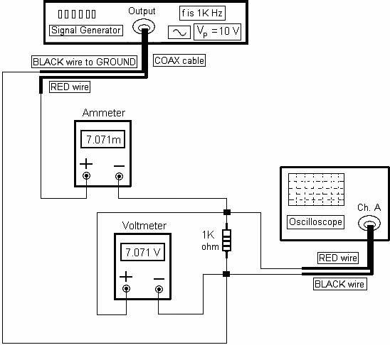
RESISTIVE CIRCUITS (R-CIRCUITS): Figure 2.3 shows a resistive circuit.
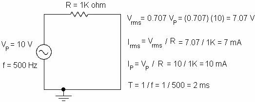
Figure 2.3
Figure 2.4 shows the input
voltage waveform of figure 2.3.
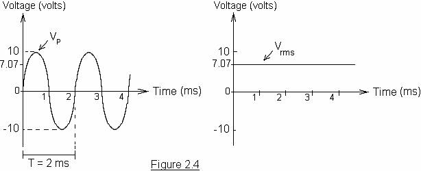
Figure 2.5 shows the input
voltage waveform is in phase with the current I of figure 2.3.
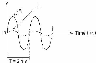
Figure 2.5
Lab
2.1 Part One
Set up the circuit (software).
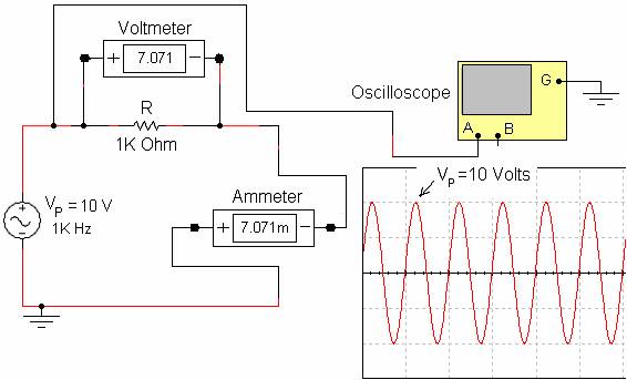
In this circuit diagram,
note the following:
VP = 10 volts, f = 1K Hz, T = (1 / f) = (1 / 1K) = 1 ms.
The voltmeter displays the
RMS value of the voltage across the resistor R.
The ammeter displays the RMS
value of the current in the circuit.
IP = VP / R = 10 / 1K = 10 mA.
Irms = (0.707) (10m) = 7.071 mA.
VR (rms) = Irms R = (7.071m) (1K) = 7.071 V.
Copyright © 2010 – New Generation Publishing
Lab
2.1 Part Two
Set up the circuit diagram
on page 9 using the following parts:
![]() Signal Generator
Signal Generator
![]() One 1K Ohm Resistor (1/4 W)
One 1K Ohm Resistor (1/4 W)
![]() Wire, 22 Gauge
Wire, 22 Gauge
![]() Oscilloscope
Oscilloscope
![]() Two BNC-to-IC hooks (1 red and 1 black)
Two BNC-to-IC hooks (1 red and 1 black)
![]() One Voltmeter
One Voltmeter
![]() One Ammeter
One Ammeter
Copyright © 2010 – New Generation Publishing