SILICON
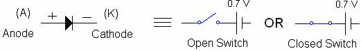
DIODE: The schematic symbol of a silicon
diode and its equivalent
model (a switch
connected to a 0.7 V battery) is shown in figure 1.3.
Figure
1.3
Note the following:
VA is the anode voltage of the diode.
VK is the cathode voltage of the diode.
VD = VA – VK.
A silicon diode works
based on the following:
If VD > 0.7, the
switch is CLOSED in figure 1.3 (diode is conducting or forward biased). If VD < 0.7, the
switch is OPEN in figure 1.3 (diode is not conducting or reverse biased).
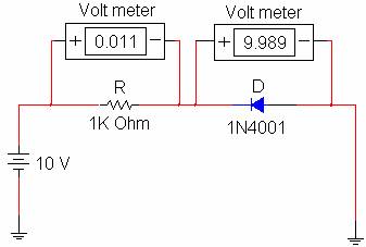
Figure 1.4 demonstrates the functions of the diode.
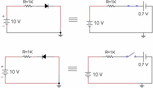
Figure
1.4
Note that when the diode is
conducting, VR = 9.3 volts (10 - 0.7) and when the diode is not conducting, VR = 0 volts. The
purpose of resistor R is to limit the current in the circuit so
the diode would not be damaged.
The diode electrical
characteristics is available in the Specification (spec) Sheet which lists all
the parameters such as current rating, power rating, peak reverse voltage
rating, and etc. Figure 1.5 shows a silicon diode with its schematic symbol.
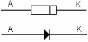
Figure 1.5
Copyright © 2012 – New
Generation Publishing
Lab
1.2 Part One
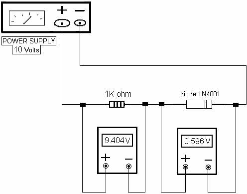
Set up the circuit (software).
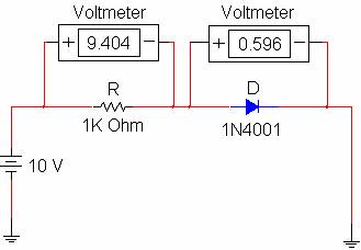
- In the first circuit, diode is forward biased
(conducting or CLOSED switch). The voltage across the diode is about 0.6
volts and the voltage across the resistor is
9.4 volts.
- In the second circuit, diode is reverse biased
(non-conducting or OPEN switch). Since the current is about zero in the
circuit, the voltage across the resistor is about zero. Therefore, all the
source voltage (about 10 V) is applied across the
non-conducting diode.
Copyright
© 2012 – New Generation Publishing
Lab
1.2 Part Two
Set up the circuit diagram
on page 5 using the following parts:
![]() 10 Volts Power supply
10 Volts Power supply
![]() One diode 1N4001
One diode 1N4001
![]() One 1K Ohm Resistor (1/4 W)
One 1K Ohm Resistor (1/4 W)
![]() Wire, 22 Gauge
Wire, 22 Gauge
![]() Two Voltmeters
Two Voltmeters
Copyright © 2012 – New Generation Publishing